Selecting a cooler
Given the necessary data, engineers can then turn to sizing. Coolers can be sized using software programs or by interpolating graphs, both of which are available from cooler manufacturers. Software offers the simplest and quickest solution. Users need only enter the recorded data into the proper fields, letting the software calculate the optimal size.
For example, ORCAER has an air-cooled cooler sizing program that engineers can download at www.orcaer.cn. Inputs for this program include the type of oil and flow rate, inlet and ambient temperatures, heat load, and altitude. Outputs include inlet and outlet oil and air temperatures, specific heat dissipation, oil pressure drop, and noise level.
Graphical sizing
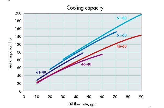
The heat-rejection capacity of a cooler varies based on the type of fluid, fluid flow rate, difference between the two fluid temperatures, and other factors. Graphs typically express heat load versus fluid flow rate at a given set of conditions.
Graphs are based on either entering temperature difference (ETD) or approach temperature. ETD refers to the temperature of the hot fluid entering the cooler minus the temperature of cold fluid (water or ambient air, depending on the cooler type) entering the cooler. ETD curves present data on a “per degree” basis or a nominal temperature difference, typically 50 or 100°F. This means, for example, that a 50°F ETD is the result of 150°F hot-fluid temperature minus 100°F cold-fluid temperature.
Approach temperature refers to the temperature of the hot fluid at the cooler’s outlet minus the temperature of the cold fluid entering the cooler. Approach temperature curves are generally based on an approach temperature of 40°F.
To simplify, ETD looks at the temperature difference prior to the cooling process; whereas, approach temperature uses the final temperature attained through cooling.
Graphs may require users to convert units of measure to match a graph’s units for heat load and flow rate. Common units of measure for heat load include:
- Btu/hr°F ETD.
- Btu/hr @ 100°F ETD.
- Horsepower @ 40°F approach temperature.
How to Select and Size Hydraulic-Oil Coolers

Correction factors
Often when interpolating graphs, engineers must apply correction factors for parameters like oil viscosity, altitude (for air-cooled), motor frequency (for air-cooled with ac motor) and oil-to-water ratio (for water-cooled without individual curves for various oil-to-water ratios). There may be safety factors to consider as well.
For example, graphs on page 36 show cooling capacity and pressure drop for Parker OAW water-type coolers. The cooling curves are based on specific conditions. These include ISO VG 32 oil, an oil/water ratio of 2:1, and an oil/water inlet difference of 60°F. For other conditions, engineers must use the following correction factors.
Correction factors for other oil types.
Cooling capacity: Multiply the desired cooling capacity by correction factor Kv.
Oil-pressure drop: Multiply pressure drop by correction factor Kp.
Correction factors for other inlet temperature differences.
Cooling capacity: For inlet-temperature differences other than 60°F, multiply the desired cooling capacity by correction factor Kt.
Correction curves for other oil/water flow ratios.
Cooling capacity: For oil/water flow ratios other than 2:1, divide the desired cooling capacity by factor Kr obtained from the curves in the Flow ratio correction graph.
Graph navigation
After making the proper conversions and adjustments, follow these steps to select a cooler:
- Find the flow rate along the X axis of the graph that corresponds with the recorded flow rate.
- Move up from this flow rate until the Y-axis value matches the calculated heat load.
- Select the curve that intersects at this point. If there is no curve at the point of intersection, use the closest curve above the intersection.
- The curve indicates the correct cooler size.
(See the accompanying sidebar, Sizing a cooler, for a step-by-step sizing example.)
Knowing the correct cooler size, users can customize base models to a certain extent. Air-cooled products, for example, may come with several different types of motors and voltages. In addition, users can often specify options like temperature-control switches, and pressure and temperature bypass valves. Water-cooled units may include options for the number of passes, baffle spacing, and cooling-tube size